Beranda
/ Diy Guitar Amp Circuit / Design And Build Your Own Tube Guitar Amp Workbenchfun Com : Ampeg a120 schematic 120 watt rms rack mount power amp.
Diy Guitar Amp Circuit / Design And Build Your Own Tube Guitar Amp Workbenchfun Com : Ampeg a120 schematic 120 watt rms rack mount power amp.
Insurance Gas/Electricity Loans Mortgage Attorney Lawyer Donate Conference Call Degree Credit Treatment Software Classes Recovery Trading Rehab Hosting Transfer Cord Blood Claim compensation mesothelioma mesothelioma attorney Houston car accident lawyer moreno valley can you sue a doctor for wrong diagnosis doctorate in security top online doctoral programs in business educational leadership doctoral programs online car accident doctor atlanta car accident doctor atlanta accident attorney rancho Cucamonga truck accident attorney san Antonio ONLINE BUSINESS DEGREE PROGRAMS ACCREDITED online accredited psychology degree masters degree in human resources online public administration masters degree online bitcoin merchant account bitcoin merchant services compare car insurance auto insurance troy mi seo explanation digital marketing degree floridaseo company fitness showrooms stamfordct how to work more efficiently seowordpress tips meaning of seo what is an seo what does an seo do what seo stands for best seotips google seo advice seo steps, The secure cloud-based platform for smart service delivery. Safelink is used by legal, professional and financial services to protect sensitive information, accelerate business processes and increase productivity. Use Safelink to collaborate securely with clients, colleagues and external parties. Safelink has a menu of workspace types with advanced features for dispute resolution, running deals and customised client portal creation. All data is encrypted (at rest and in transit and you retain your own encryption keys. Our titan security framework ensures your data is secure and you even have the option to choose your own data location from Channel Islands, London (UK), Dublin (EU), Australia.
Diy Guitar Amp Circuit / Design And Build Your Own Tube Guitar Amp Workbenchfun Com : Ampeg a120 schematic 120 watt rms rack mount power amp.. A guitar amplifier is an electronic circui t that is usually housed in a wooden cabinet to strengthen the weak electrical signal from an electric or bass guitar to produce sound through one or more loudspeakers. But building a reverb module means you can add a couple of additional controls, and i'm adapting the circuit for dwell and tone, as well as level. Although they are cheap they are not good enough to produce the best of a basic guitar amp. When we carefully consider found that amplifier circuit consists of two sets are: So we are going to use another ic called tea2025b wh…
It goes into the area marked in, above. By alex lynham march 31, 2021. The power transformer and output transformer are attached to the other side of the chassis. Diy and the boutique amp builder If you are going to house your amplifier in a tin, be sure to use electrical tape or heavy card stock to insulate the circuit from the metal bottom.
Sam Technology Professionals Build A 20w Guitar Amp Diy from 4.bp.blogspot.com It is guitar amplifier circuit diagram with pcb layout. A guitar amp kit is basically a diy amplifier. Most people building guitar amp based on the lm386 ic which is noise prone or the tda2030 lack of sound. First, it's important to note that there are actually two types of clipping: But building a reverb module means you can add a couple of additional controls, and i'm adapting the circuit for dwell and tone, as well as level. A guitar amp has a very limited frequency range. See more ideas about guitar, guitar amp, diy guitar amp. The frequency range of a speaker system tells what it can handle.
It is guitar amplifier circuit diagram with pcb layout.
See more ideas about amplifier, diy guitar amp, circuit. Although they are cheap they are not good enough to produce the best of a basic guitar amp. A guitar amp has a very limited frequency range. Set the gain using preset vr2. 'dwell' sets the signal level entering the reverb circuit, and tone is a simple treble roll. We are always adding more as we find them so check back often. The characteristics of the circuit as shown in figure 1. Amplifier circuit april 11, 2016 here the circuit design for diy guitar transistor preamp. The circuit is simple, so the building this amp in a normal size enclosure wouldn't have posed much of a problem. A 9v regulated dc power supply is the vital portion of this circuit. The frequency range of a speaker system tells what it can handle. See more ideas about guitar, guitar amp, diy guitar amp. Space is restricted on amplifier control panels, so reverb level is usually the only control you get.
Since i'm using the lm386 the circuit is pretty simple, and can be found in the datasheet of the lm386, i used the circuit of bass boost, i know that the sound of the guitar is based on high tones, but as i said in the beginning this is actually a general purpose amplifier, so if you are planning to use it as a guitar amplifier just change the circuit for another suggestion in the datasheet. V1 preamp tube on right, v2 power tube in center, v3 rectifier tube on left. The circuit is designed for input levels of up to 3 v. However, shoehorning it into a box 7 1/4 x 4 1/2 x 2 1/4 inches turned out to be tricky. But building a reverb module means you can add a couple of additional controls, and i'm adapting the circuit for dwell and tone, as well as level.
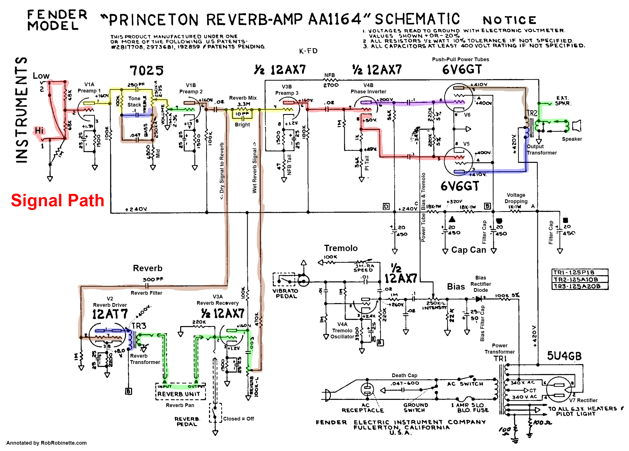
Reading Schematics from robrobinette.com We are always adding more as we find them so check back often. The circuit is simple, so the building this amp in a normal size enclosure wouldn't have posed much of a problem. It is wisely designed with power output at 200 watt in super bridge model so help to you have a high quality circuit in cheap. It can be used as buffer at the beginning of a chain of effects. Although they are cheap they are not good enough to produce the best of a basic guitar amp. The circuit 'electric guitar preamp circuit' is set up in a metallic case. Over this level distortion rises, but that may be, naturally, a decent outcome having guitar music. Here we've listed our collection of guitar amplifier schematics.
Set the gain using preset vr2.
It is guitar amplifier circuit diagram with pcb layout. Amplifier circuit april 11, 2016 here the circuit design for diy guitar transistor preamp. So we are going to use another ic called tea2025b wh… When we carefully consider found that amplifier circuit consists of two sets are: The circuit is simple, so the building this amp in a normal size enclosure wouldn't have posed much of a problem. Diy and the boutique amp builder High voltage to the left and 12.6vac for the heaters to the right. A guitar amplifier is an electronic circuit that is usually housed in a wooden cabinet to strengthen the weak electrical signal from an electric or bass guitar to produce sound through one or more loudspeakers.a guitar amp has a very limited frequency range. If you are going to house your amplifier in a tin, be sure to use electrical tape or heavy card stock to insulate the circuit from the metal bottom. If you need a guitar amp schematic for your amp repair that is not listed here, contact us and we'll try to locate it. A guitar amp kit is basically a diy amplifier. What you need to use one of these kits is time, which thankfully there's a lot of that these days, and some technical knowledge. Build your own diy guitar amp from scratch.
A guitar amplifier is an electronic circui t that is usually housed in a wooden cabinet to strengthen the weak electrical signal from an electric or bass guitar to produce sound through one or more loudspeakers. A 9v regulated dc power supply is the vital portion of this circuit. It consists of a circuit of two transistors and four controls that can be vary the level of the treble, bass, gain, and total salidad circuit (volume). Most people building guitar amp based on the lm386 ic which is noise prone or the tda2030 lack of sound. The distortion circuit distortion is an effect a musician can use to add a fuzzy tone to their guitar's sound, typically by increasing their gain.
Guitar Dreamer Diy Single 12ax7 1 4w Tube Amp from 4.bp.blogspot.com You can use this circuit in any project where you need to amplify sound. We are always adding more as we find them so check back often. 'dwell' sets the signal level entering the reverb circuit, and tone is a simple treble roll. See more ideas about guitar, guitar amp, diy guitar amp. Designed with extra capacitors to reduce inpu. It can be used as buffer at the beginning of a chain of effects. A basic understanding of pickups, potentiometers, capacitors and switches is all you need to get creative and take more control of your instrument's voice on an electronic level. If you need a guitar amp schematic for your amp repair that is not listed here, contact us and we'll try to locate it.
The distortion circuit distortion is an effect a musician can use to add a fuzzy tone to their guitar's sound, typically by increasing their gain.
Set the gain using preset vr2. 'dwell' sets the signal level entering the reverb circuit, and tone is a simple treble roll. A 9v regulated dc power supply is the vital portion of this circuit. The frequency range of a speaker system tells what it can handle. It consists of a circuit of two transistors and four controls that can be vary the level of the treble, bass, gain, and total salidad circuit (volume). It can be used as buffer at the beginning of a chain of effects. High voltage to the left and 12.6vac for the heaters to the right. In our project here, we'll create a clipping circuit by using two diodes. The characteristics of the circuit as shown in figure 1. Here we've listed our collection of guitar amplifier schematics. If you are going to house your amplifier in a tin, be sure to use electrical tape or heavy card stock to insulate the circuit from the metal bottom. Space is restricted on amplifier control panels, so reverb level is usually the only control you get. It is guitar amplifier circuit diagram with pcb layout.